
3. How do you think the motor works? Discuss this question with the others in your group.
B. Mounting the Armature
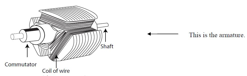
1. Use the diagram below to locate the commutator—the split ring around the motor shaft.
2. Look at the drawing on the next page and find the brushes—two short ends of bare wire that make a "V". The brushes will make electrical contact with the commutator, and gravity will hold them together. In addition the brushes will support one end of the armature and cradle it to prevent side-to-side movement.
3. Using the cup, the two rubber bands, the piece of bare wire, and the three pieces of insulated wire, mount the armature as in the diagram below.
4. You will have to tape together the two #20 insulated wires to make the brushes. The commutator—the split ring on one end of the motor shaft—will rest on the brushes.
5. Using the rubber bands, mount the wires on the plastic cup as shown in the drawing.
6. Use the small compass to find the north and south poles of the ceramic magnets.
7. Hook up the battery and bulb to the commutator leads. How does the bulb help you understand if the circuit is working?
8. With the armature mounted as in the diagram above, bring up the two magnets—stuck together—and get the armature spinning.
Contact: Sammy
Skype:
Tel:
Email: sammyfu@electricmotorscn.com
Add: Building 3, No. 2 Chaoheng Road, Chashan Town, Dongguan City, Guangdong Province
 Sammy
Sammy