
This step is to build the PM brushless DC motor model and determine the design parameters. The model contains four portions which include the armature winding, permanent magnet, magnet frame, and stator. Before carrying out motor analyses, it is required to build an effective motor model based on the motor’s own structure and the dimensions of each of the motor components. The coils were built in bump shapes which attach to the silicon steel sheets for the purpose ofsimplicity. This PM motor model comprises
1) stator,
2) rotor motor case,
3) permanent magnet, and
4) coil armature winding. The resulting grids of the PM motor are shown in Figure 4 in which triangular grids were used for modeling with the emphasis on solving for the air gap. Dimensions of each portion of the brushless DC motor in the present work and their related electromagnetic parameters are shown in Table 3. Considering characteristics of the brushless DC motor’s magnetic field distribution, a two-dimensional model of static magnetic field was used for analysis and the procedure is described as follows.
1) Create the model,
2) Configure boundary conditions,
3)Configure solver parameters, and
4) Create meshes. Based on the domain size and engineering units
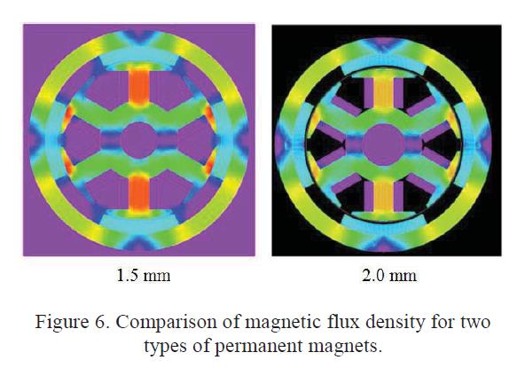
defined for the model, a brushless DC motor model was created in this study. As for the settings of boundary conditions, symmetrical boundaries were adopted and the boundary values were assigned as 0. At the initial state, firstly we carried out the analysis of motor conditions with no load and thus the motor’s armature winding current was also assigned as 0. When configuring the solver parameters for torque analyses, the rotor motor case and the permanent magnet are regarded as the objects that are subject to forces. The inductance values configured for the winding connections are as shown in Figure 6. When creating grids, it is required to apply adequate sizes to the grids for simulation and various cases of different mesh sizes including 0.1mm, 0.5mm, and 1mm were tested. The most accurate result was obtained when the grid size is 0.1mm. However, the required time to convergence is much longer. When the grid size is 1mm, the calculation time was shortened but the calculation result was not accurate enough since the grids were coarser. As a result, 0.5mm grid size was determined to be the optimal one in this study.
Contact: Sammy
Skype:
Tel:
Email: sammyfu@electricmotorscn.com
Add: Building 3, No. 2 Chaoheng Road, Chashan Town, Dongguan City, Guangdong Province
 Sammy
Sammy